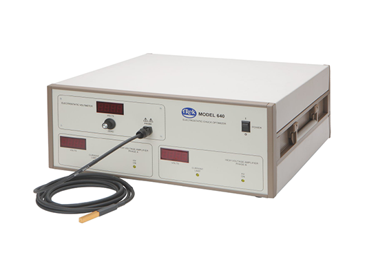


Trek’s Model 640 Electrostatic Chuck Optimizer system is a diagnostic tool which enables evaluation and optimization of waveforms and voltages for electrostatic chucks/clamps in order to minimize de-clamp time, maximize clamp force, and achieve optimum wafer processing for ESC systems.
Model 640 combines two amplifiers (for two-phase voltage combinations) and a waveform generator, which can be independently programmed and configured to investigate, research, and discover the perfect power supply and waveform recipe to efficiently drive an ESC application. An electrostatic voltmeter (ESVM) is included to monitor residual voltage from the clamping/de-clamping process.
Typical Applications Include
Electrostatic-driven handling of materials
Semiconductor wafer processing
Non-mechanical transfer of flat panels or other processing materials sensitive to mechanical clipping
Features and Benefits
Enables the creation of customized waveforms to be simple yet powerful, to generate the most complex waveforms that can be envisioned by the user
The product’s software accepts parameters via arbitrary data input, pre-programmed waveforms, or companyspecific CSV files
Utility is enhanced via three individually programmed stages to build the waveform: (1) Clamp Signal Stage, (2) Processing Signal Stage (with options to “loop” the process cycle), and (3) De-clamp Stage
Test data is recorded and presented in numerical and graphical format with a color coded display
The graphs can also be used to troubleshoot mechanical and electrical problems within an ESC operation
NIST-traceable Certificate of Calibration provided with each unit
CE Compliant
Model 640 Specifications
Outputs
Output Phasing
Phase A Output Voltage Range:0 to ±2 kV DC or peak AC (4 kV p-p)
Phase A Output Current Range:0 to ±5 mA DC or peak AC (10 mA p-p)
Phase B Output Voltage Range:0 to ±2 kV DC or peak AC (4 kV p-p)
Phase A Output Current Range:0 to ±5 mA DC or peak AC (10 mA p-p)
Amplifier Performance [each phase]
Large Signal Bandwidth (1% distortion):DC to greater than 1.2 kHz
Small Signal Bandwidth (-3 dB):DC to greater than 5 kHz
Slew Rate:Greater than 15 V/µs
Settling Time:less than 300 µs for 0 to 2 kV step
DC Accuracy:Better than 0.1% of full scale
Offset Voltage:Less than 500 mV
Output Noise:Less than 100 mV rms*
Drift with time:Less than 100 ppm/hour, noncumulative
Drift with Temperature:Less than 350 ppm/°C
Output Voltage Monitor (Back Panel Connector)
Drift with Temperature:Less than 350 ppm/°C
Features
Clamped Wafer Detection Feature (Thresholds are set by the program) :
To indicate wafer clamping events, the capacitive currents generated by a low voltage sine wave, super-imposed on the Phase A and Phase B outputs, are monitored but can be disabled through the program. The superimposed waveform is used to indicate a no wafer, wafer present or wafer clamped status
Capacitive Load Select:
Clamped capacitance status range can be selected by the program for 0 to 10, 20 or 30nF (phase to phase) depending on the system and electrostatic clamp physical configurations
Mechanical
Dimensions:43.7 mm H x 421.6 mm W x 457.3 mm D (1.72” H x 16.6” W x 18” D) 1U rack enclosure
Panel Width:482.6 mm (19”)
Weight: 8.5 lbs (3.86 kg)
Connectors: 15-pin “D” ITT Canon used by remote device to control/monitor the unit, 9-pin “D” ITT Canon RS232, 3-Pin FCT “D” High-Voltage, standard type-A USB, Ethernet (optional) and Front Panel
Power ON/OFF: 2-position rocker switch
Operating Conditions
Temperature: 0°C to 35°C (32°F to 104°F)
Relative Humidity:To 85%, noncondensing
Altitude: To 2000 meters (6561.68 ft.)
Electrical DC Input Receptacle:
2.0 mm locking DC jack; center contact is positive and shell is negative (receptacle mates with Switchcraft S761K plug)
Ground Receptacle: Ground stud
Power Requirements: 24 V DC, 1.7 A
Supplied Accessories
Operator Manual, SW PN: 24010
USB Cable HV Connectors PN: BA103 PN: B8084R, B8085R, B8088R, B8089R
DC Plug ( S761K) Switchcraft PN: BA119R
Line Cord, Fuses Selected per geographic destination
Optional Accessories
90-264 V AC to 24 V DC Power Adapter: PN: IK045
Note
Trek Model 646, a ±3 kV version of this instrument, is also available.
Please contact the factory for more information.