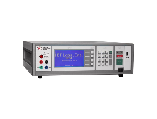


A Megohmmeter/IR Tester with digital display used for high-accuracy measurements of high resistance and insulation resistance. It includes a programmable limit for pass/fail testing, USB host port, and RS-232 interface.
General Features
Proven over many years in the field
Measurement range up to 100 TΩ
0.5% measurement accuracy
High-visibility blue LCD graphical display
Automatic ranging
Automatic zeroing of test leads
Direct reading of Insulation Resistance
RS-232, I/O port, and USB interfaces
Optional IEEE-488 to RS-232 Adapter Programmable test voltage from 1 to 1000 Vdc
Programmable test times
512 MB of internal storage of test-setup and results
CSV fi le format for easy use with Microsoft Excel
Limit entry for Pass/Fail testing
Keypad lockout with password protection
DESCRIPTION
Precision measurements:
The 1865+ provides resistance measurement capability over a range of 1 kΩ to 100 TΩ (test voltage dependent), with a basic accuracy of 0.5%. To meet the test requirements for a wide range of devices, the test voltage is fully programmable up to 1000 Vdc. Sensing the proper resistance measurement range is done automatically, eliminating setup errors. The operator can initiate an automatic test leads zeroing routine in order to eliminate lead or fixture errors.
Easy to use:
The 1865’s menu programming system, simple controls and indicators combine for efficiency of test and productivity. Its multi-function keypad provides the operator with an easy way to program and make measurements.
Pass/Fail:
Measured results are automatically compared to an operator-programmed limit for pass/fail testing. Pass/Fail indicator lights or a pass/fail output from the instrument's I/O interface give a clear indication of the measurement results.
Program data storage:
Test setup conditions and measured results can be stored in CSV format for easy use with Microsoft Excel. Storage options include:
512 MB of internal instrument memory,
A computer (via the IEEE interface)
A flash drive (via the USB port) New programs can also be uploaded via the IEEE interface or the USB port
Automated testing:
For automated system applications, the 1865+ includes an I/O interface connection with remote start and pass/fail outputs. An optional IEEE-488 interface is also available (or can be added later), which enables the 1865 to be remotely controlled by a computer.
Display mode (Resistance or Current):
The operator may select display mode to read either measured resistance or measured current.
Safety features
For protection of the operator, the 1865+ provides safety features such as current limiting, a safety interlock, and a warning indicator when high voltage is active
Resistance range:
1 kΩ (103 Ω) to >100 TΩ (1014 Ω)
No of ranges:
7 manually settable plus auto-ranging
Resistance range for set voltage
Voltage Setting | Rmin | Rmax |
1Vdc | 1 MΩ (106Ω) | 10 GΩ (1011Ω) |
10Vdc | 100 kΩ (105Ω) | 1 TΩ (1012Ω) |
100Vdc | 10 kΩ (104Ω) | 1 TΩ (1013Ω) |
1000Vdc | 1 kΩ (103Ω) | >100 TΩ (1014Ω) |
Voltage range:
1 to 1,000 volts, programmable in two ranges
Voltage accuracy at front panel connectors:
1 - 100 V: ±[(1% of setting + 1 V) Resolution: 25 mV
100 - 1,000 V: ±[(1% of setting + 2 V) Resolution: 250 mV
Resistance accuracy:
±[0.45% +{(RX/VX)(0.0005FS + 2pA) + 30Ω/RX}100%]
where:
RX = Measured resistance in ohms
VX = Programmed voltage in volts
FS = Full scale current range in amperes
Measuring current:
0.1 pA (10-13 A) to 1 mA (10-3 A)
Current accuracy at front panel connectors:
1 nA to 1 mA ±[0.5% + (0.0005 FS + 2 pA)]
100 pA to 1 nA ±[1% + (0.0005 FS + 2 pA)]
1 pA to 100 pA ±[10% + (0.0005 FS + 2 pA)]
Short-circuit current:
<2 mA
Input impedance:
5 kΩ, ±5%
Output voltage impedance:
1 kΩ, ±5%
Test cycle:
Manual: Charge, Measure, Discharge
Automatic: Charge time: 0 - 300 seconds
Dwell time: 0 - 300 seconds
Measure time: 0 - 999 seconds
Discharge time: 0 - 300 seconds
Measurement limits:
Pass/Fail (1 limit)
Interfaces:
Standard: RS-232, I/O port with safety interlock
USB Host Port for Data/Program storage
Optional: IEEE-488
Input terminals:
Four sheathed banana jacks, front-mounted (with optional rear-mounting)
+ unknown (red)
- unknown (black)
guard (blue)
ground (green)
Additional features:
• Fully programmable via on-screen menu
• Internal zeroing
• 512 MB of internal memory for storing test conditions and results
• Measurement averaging (1-400 readings)
• Stop on pass
• Safety interlock
• Keypad lockout
Power:
• 90 - 250 V
• 47 - 63 Hz
• 40 W max
Display:
LCD graphic display
High-Voltage warning indicator
Pass/Fail indicator
Environmental conditions:
Operating temperature: 0ºC to 50ºC, <45% RH
Storage temperature: -40ºC to 70ºC
Altitude: < 2000 m
ORDERING INFORMATION
1865+ Megohmmeter/IR Tester
Includes:
• Instruction manual
• Calibration certifi cate traceable to SI
• AC power cable
• 100 kΩ capacitor current-limiting adaptor
• 1 MΩ capacitor current-limiting adaptor
• Interlock
Optional Accessories
• 7000-23-120V IEEE to RS-232 Interface Adapter
• 7000-23-240V IEEE to RS-232 Interface Adapter
• 1865-03 Rear panel input (factory installed)
• 1865-50 Rack mount kit
• 1865-51 Shielded lead set
• 1865-52 Component test fi xture
• Calibration data