


Trek’s Model 646 software-driven Electrostatic Chuck Supply offers an array of features that provide significant benefits while accommodating a variety of demanding applications. Documented use shows that customers have seen increases in efficiency and throughput equal to three times that of other supplies. Additionally, the Model 645 virtually eliminates sticky wafer and wafer popping issues, thus ensuring better control over particle contamination.
Given the versatility and performance of the Model 646, it can be used in multiple unique tools/processes, thus eliminating the need to specify a new supply for each unique tool/process in a facility.
Typical Applications Include
Electrostatic-driven handling of materials
Semiconductor wafer processing
Non-mechanical transfer of flat panels or other processing materials sensitive to mechanical clipping
Features and Benefits
Supports both Coulombic and Johnsen-Rahbek ESC technologies
User configurable for custom clamp and declamp sequences and wave shapes
Electrostatic chuck profiles can be uploaded to the unit and stored internally via a user-friendly software interface
Documented reduction of backside gas errors, increased throughput, and elimination of sticky/popping wafers
Lockable front panel control interface
Ability to control parameters such as over-current, wafer-present and wafer-clamped thresholds, clamp voltage, offset voltage and internal or external amplitude/offset control
Wafer detection includes no wafer, wafer present or wafer clamped status
Includes in-process-adjustable amplitude/offset and output-control versatility
Output can be controlled by back panel I/O, serial computer command or front panel controls
NIST-traceable Certificate of Calibration provided with each unit
CE Compliant
Outputs
Simultaneous HighVoltage Outputs:Two simultaneous high-voltage outputs (Output Phase A and Output Phase B) of equal magnitude and opposite in polarity relative to an offset voltage
Output Phasing
Output Voltage A (Reference Phase): 0 to ±3 kV
Output Voltage B: 0 to ±3 kV (Phase B =[-1] x Phase A)
Offset Voltage (This feature can be disabled through the program):
Each DC output voltage (Phase A and Phase B) is ramped up and down with symmetrical rise and fall times, or they can be programmed with the user's custom clamping and declamping waveforms. The clamping process is initiated in response to the Clamp On/Off control. The polarity of each output reverses to the opposite polarity after each Clamp On/Off cycle.
Output Waveshape:
Each DC output voltage (Phase A and Phase B) is ramped up and down with symmetrical rise and fall times, or can be programmed with the user’s custom clamping and declamping waveforms
Output Voltage Range: 0 to ±3 kV DC, maximum
Output Current: 0 to ±6.5 mA DC with peak capability of 10 mA
Input
Setting the HighVoltage Amplitude: HV magnitude can be controlled either externally or internally to the unit
Setting the Offset Voltage: Offset voltage may be controlled externally or internally to the unit
Output Voltage Monitor (Back Panel Connector)
Scale Factor : 1 V/300 V
Phase B DC: Accuracy better than 0.5% of full scale
Offset Voltage: Less than 10 mV
Output Noise: Less than 50 mV rms*
Steady State Voltage Leakage Current Monitor
Scale Factor: 1V / 1 µA
DC Accuracy: ± 0.1 µA
Output Noise: Less than 50 mV rms*
Features
Interlock: Connections are provided to support an interlock safety configuration. In the event that the interlock is open, the high-voltage generation circuits are shut down
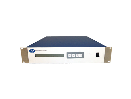
Digital Display: 40X2 LCD character display shows various system functions such as Set Voltage, Output Voltage and Capacitance Monitor
Clamped Wafer Detection Feature (Thresholds are set by the program) :
To indicate wafer clamping events, the capacitive currents generated by a low voltage sine wave, super-imposed on the Phase A and Phase B outputs, are monitored but can be disabled through the program. The superimposed waveform is used to indicate a no wafer, wafer present or wafer clamped status
Capacitive Load Select:
Clamped capacitance status range can be selected by the program for 0 to 10, 20 or 30nF (phase to phase) depending on the system and electrostatic clamp physical configurations
Mechanical
Dimensions:88.1 mm H x 431.8 mm W x 531.9 mm D (3.47” H x 17” W x 20.9” D) 1U rack enclosure
Panel Width:482.6 mm (19”)
Weight: 8.5 lbs (3.86 kg)
Connectors: 15-pin “D” ITT Canon used by remote device to control/monitor the unit, 9-pin “D” ITT Canon RS232, 3-Pin FCT “D” High-Voltage, standard type-A USB, Ethernet (optional) and Front Panel
Power ON/OFF: 2-position rocker switch
Operating Conditions
Temperature: 0°C to 35°C (32°F to 104°F)
Relative Humidity:To 85%, noncondensing
Altitude: To 2000 meters (6561.68 ft.)
Electrical DC Input Receptacle:
2.0 mm locking DC jack; center contact is positive and shell is negative (receptacle mates with Switchcraft S761K plug)
Ground Receptacle: Ground stud
Power Requirements: 24 V DC, 2.0 A
Supplied Accessories
Operator Manual, SW PN: 24013
USB Cable HV Connectors PN: BA103 PN: B8076R
DC Plug ( S761K) Switchcraft PN: BA119R
Line Cord, Fuses Selected per geographic destination
Optional Accessories
90-264 V AC to 24 V DC Power Adapter: PN: IK045
Note
Trek Model 645, a ±2 kV version of this instrument is also available.
Please contact the factory for more information.