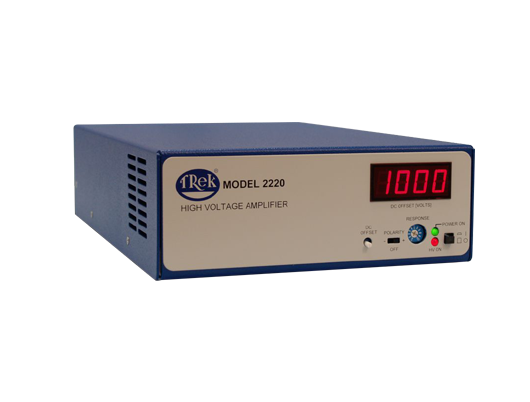


Trek’s Model 2220 is one of several models within our 2200series of high-voltage 40 W amplifiers. Provided at an attractive price and offering high performance, the unit incorporates DC stability, wide bandwidth and well regulated/controlled AC output signals. It also features full four-quadrant class AB all-solid-state output stages, DC offset adjustment with front panel metering, and autorecovery shutdown to protect the output from being overpowered. The instrument stage sinks or sources current into reactive or resistive loads throughout the output voltage range making it ideal to achieve the accurate output response and high slew rates demanded by reactive loads.
Features and Benefits
Four-quadrant output for driving capacitive loads
DC offset adjustment with front panel metering
Auto-recovery shutdown protects the output from being overpowered
Low output noise for ultra-accurate outputs
All solid-state output stages
RoHS compliant
HALT Tested
CE compliant
Model 2220 Specifications
Performance
Output Voltage Range:0 to ±2 kV DC or peak AC
Output Current Range:0 to ±10 mA DC or ±20 mA peak (for 5 ms minimum)
Input Voltage Range:0 to ±10 V DC or peak AC
Input Impedance: 10 kW, nominal
DC Voltage Gain:200 V/V
DC Voltage Gain Accuracy: Better than 0.5% of full scale
Offset Voltage:Less than 1 V
Output Noise:Less than 50 mV rms*
Slew Rate(10% to 90%, typical):Greater than 100 V/µs
Large Signal Bandwidth (-3 dB)
DC to greater than 7.5 kHz
Small Signal Bandwidth (-3dB)
DC to greater than 50 kHz
Settling Time to 1% Less than 50 µs for 0 to 2 kV step
Internal Capacitance (HV Output):300 pF
Automatic Power Limit:Limits internal power dissipation for protection from overheating
Stability:Drift with Time Less than 300 ppm/hr, noncumulative
Drift with Temp Less than 180 ppm/°C
Voltage Monitor
Noise: 5 mV rms
Ratio: 1/200th of the high voltage output
Current Monitor
Ratio: 0.4 V/mA
DC Offset Adjust: Better than 2% of full scale
Features
Digital Enable:
A BNC connection for a TTL compatible signal to turn ON/OFF the high voltage output is provided. TTL high (or open) turns off the HV output; TTL low turns on the HV output.
Response:
A graduated 1-turn panel potentiometer is used to optimize the AC response for various load parameters.
High Voltage LED: Front panel red LED illuminates when the high voltage is on.
Mechanical
Dimensions: 85 mm H x 205 mm W 325 mm D (3.3” H x 8.1” W x 12.8” D)
Weight: 2 kg (4.4 lb)
HV Connector: SHV Connector
BNC Connectors: Amplifier Input, Voltage Monitor, Current Monitor, Digital Enable
Operating Conditions
Temperature: 0°C to 40°C (32°F to 104°F)
Relative Humidity: To 85%, noncondensing
Altitude: To 2000 meters (6561.68 ft.)
Electrical
Input Power: 90 to 265 V AC, at 50/60 Hz
Output Power: 24 V DC, regulated at 1.75A maximum
HV Cable: 2 m, 30.8 pF per foot
Supplied Accessories
Operators’ Manual PN: 23447
AC Adapter PN: L5215R
HV Output Connector (SHV Mating Connector) PN: 43874R
Optional
Accessories None
Note
The output cable supplied with this instrument uses a coaxial cable that has 30.8 pF/ft of capacitance at 1 kHz nominal. This cable capacitance must be factored in as a portion of the load and will reduce slew rates and large signal bandwidth. In applications that require maximum performance it is suggested that the supplied high voltage coaxial cable be kept as short as possible to reduce capacitance. Another option is to cut the coaxial cable short and add two break out leads (1 for shield [ground] and 1 for the center conductor) for the connection to load.